Sofle RGB Build Guide, Part 1
Sofle RGB Build Guide (Part 1)
This guide serves as a way to document my experience building the Keyhive Sofle RGB split keyboard. I’ll include notes and images where appropriate to help guide any other lost soul, shouldyou wish to thread this path as well.
TL;DR
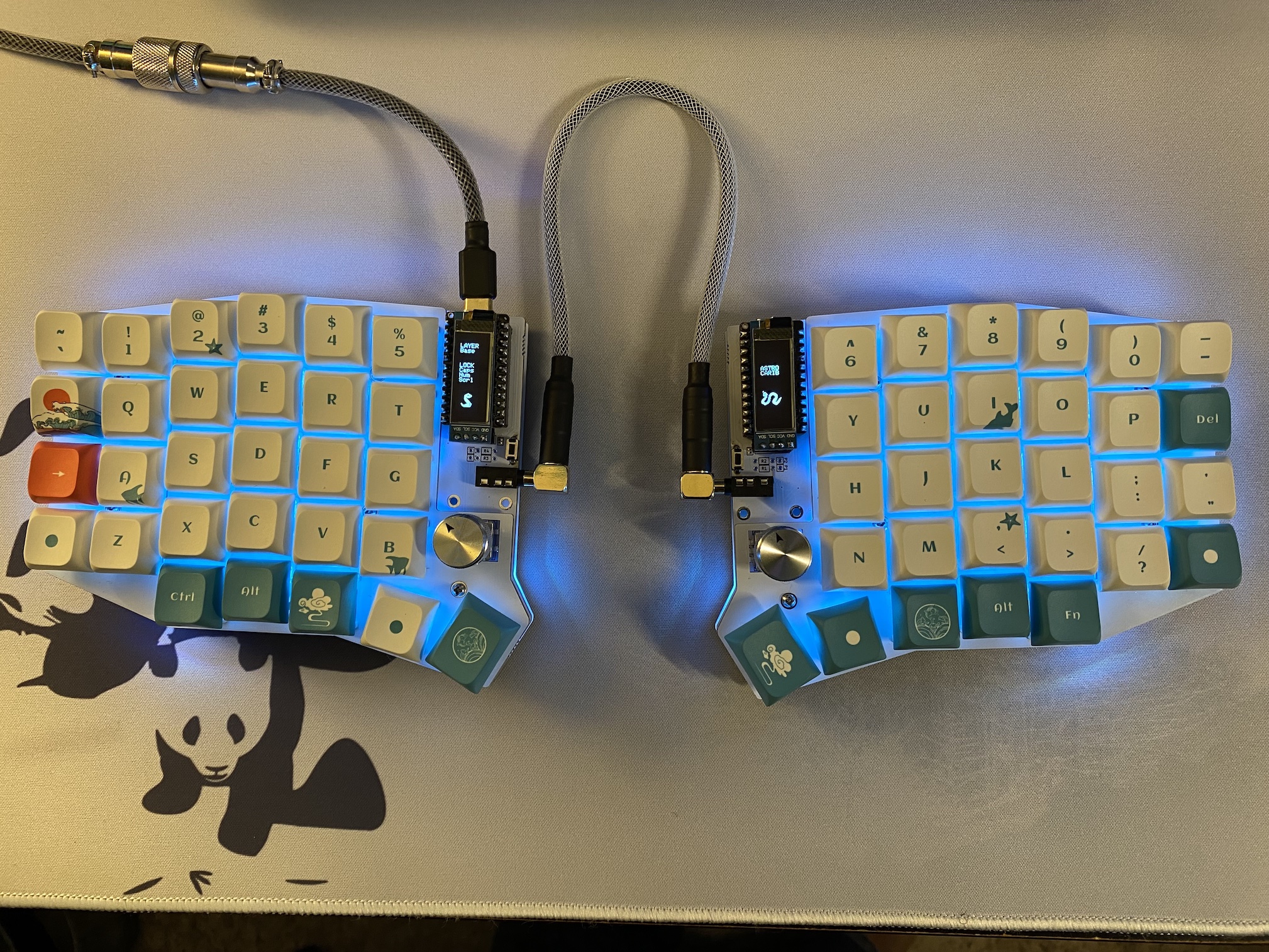
I did a thing; I built a DIY split, column staggered, ortholinear keyboard. The Keyhive Sofie RGB called to me, I answered, and begun writting notes on the trials and tribulations of building and configuring this thing.
This is part 1 of X, because I realized that I had way too much to put into one entry. Part 1 covers soldering the components and basic flashing for testing your LEDs and keys after everything is soldered.
Motivation
So, why on Earth did I decide not just to build a keyboard kit, but a split one at that?? Well, for one, I wanted to get my hands a little dirty and not just buy a complete/pre-made keyboard. Besides, some of these bad boys can be pretty pricey! Also, underneath it all, I also wanted to learn to type. That’s right, I never learned to type proper, and have learned to rely on part muscle memory and part quick hen-pecking to get the job done. It would be nice if I actually learned to type like I should have all those years ago!
So why split keyboard? I have heard wonders about using the split keyboard form factor and the saving grace that may save repetive action injuries (like typing) and carpal tunnel, so I decided to give it a try.
OK, well why build your own? Well, I love to tinker, and I wanted to work on something that had an end-goal to it; I’m good at picking and working at pieces separately, but I need more practice creating something useful from all said bits. Besides, I had a largely unused RadioShack soldering iron (yes, THAT RadioShack) so I decided it was time to do some dirty work.
Let me clear up something from the start; this isn’t a from-scratch build. I’m not that much of a genious yet :). For this, I bought a DIY kit from Keyhive called the Sofle RGB, which incudes at it’s most basic a pair of PCBs, FR4 plates, and bottom covers. All the DIY bits and pieces are included, such as the LEDs (underglow and per key), diodes, Kailh sockets, rotary encoders and knobs, TTRS jacks and reset buttons. Alright, enough of this; on to the build notes!
A Helpful Note…
There is a point in the guide on soldering the leds where
there is a reference to test each LED as you go. For quite a while, I had no idea what
this meant, as the guide isn’t terribly clear on this. There were two specific things that
I did out of order/different from the guide that I thought would be noteworthy: 1) LED
order consideration, and 2) Flashing and soldering the controller before soldering the
LEDs. This may be quite obvious to the experts among us, but it took me way too long to
figure this out during my build.
I’ve included a Gotcha section below with relevant information once you get to it in the build guide.
Build Guide
The build guide for the Sofle RGB should be fairly straightforward, but there can be a few gotchas for the soldering uninitiated (like I certainly consider myself to be). Based on the most current commit of the guide (as of the publishing date of this post, Aug 5, 2021); step #1 requires soldering the majority of the kit’s included components up front. For this step, I cannot say this enough; be patient, go slow, and check your work often.
Begin by lightly tinning (placing a small amount of solder) on the pads for all the components in this step. Additional notes below.
👉🏽 Diodes
Tin one side of the pad for the intended diode, and verify the correct position of the diode. Solder and position the diode, and once satisfied, solder the other side of the diode.
👉🏽 Underglow LEDs
These can be a pain, because of the relatively tiny terminals on the LED that needs soldered. I found it helped to tin all four pads if the PCB where the LED is intended to sit, and line the LED on top, verifying the corrent orientation. Then lightly apply some pressure on the LED, and carefully flow the pre-applied solder to each terminal on the LED. See LED Order Gotcha below for some tips. For testing as you solder, see Flashing/Soldering Gotcha for tips on getting setup.
👉🏽 Per-Key LEDs
Same procedure applies, really. I lightly tin all contacts, place the led in the appropriate orientation, appl light pressure, and then flow the solder. See LED Order Gotcha below for some tips. For testing as you solder, see Flashing/Soldering Gotcha for tips on getting setup.
👉🏽 Kailh Hotswap Sockets
This is pretty straightforward; just proceed as instructed in the build guide.
At this point, you should pretty much have a working keyboard! Slap some switches on it, and then use a keyboard tester like VIA Online to test that all the positions work. If you find that a key isn’t working, recheck your soldering by reflowing the connection, and making sure that none of the pins on the switch were bent on seating the switch. Again, be patient and take your time!
We’re almost done soldering!
👉🏽 Reset Button
You got it! Solder the reset button! Make sure that the button is soldered on the top of the PCB for easier access. You’ll need this button to reset the controller before flashing updated software to it.
👉🏽 OLEDs
As for the controllers, I opted to use sockets so that I could remove and replace them at leasure without worrying about frying the PCB trying to remove them.
Note that opting to use sockets will make it necessary to use longer standoffs to put the OLED covers that come with the kit (~12mm; these standoffs are not included in the kit).
👉🏽 TTRS Jacks
As it says on the tin.
👉🏽 Encoders
These shoud be straightforward; just follow the guide!
👉🏽 Switches
Seat your switches of choice onto the hotswap sockets, taking care not to bend the pins as you do.
The End (of Part 1)
Finally! The moment of truth! Install your switches and test as you go along. But at this point, you may have to reflash your keyboard so you can update to the proper firmware, one which includes proper support for the encoders and weird layout (you know, because of the encoders!).
Tune in to Part 2 of this build guide to follow along with the firmware side of this journey!
Gotchas
👉🏽 Flashing/Soldering Controller
The only way to test the LEDs as you solder them unto the the PCB, is to plug it in. And the only way to plug your little Frankenstein of a keyboard in to flash and then solder the controller onto the PCB. For one, note that it is possible to install the controller the wrong way. My build uses the Elite-C v4 controller, and I completely missed the correct orientation from the photos in the build guide. This lead me to panic into thinking that I burned the controller, and desperately trying to desolder the controller from the PCB.
Save yourself the trouble and use a socket to install the controller. Mouser Electronics is a great place to source these components, and I used these sockets and pins to seat the controllers, making it easy to remove and replace in the future.
To flash the controller, you’ll need the QMK Toolbox and a firmware file. For this first round all you want to test is your LEDs, so a proper keymap isn’t quite necessary just yet. Flashing the controller should be fairly pain-free using the QMK guide on flashing; when asked for a firmware to flash, use the one provided by Keyhive as a starting point for testing.
👉🏽 LED Order
LED order was another thing that bypassed my synapses completely. When I first started installing the LEDs (after figuring out that I could/should install the controllers to test the LED) I though I burned some of the LEDs as warned in the guide. Here’s the thing; LED order is important in testing. Meaning that the LEDs are connected in series, and if the LED isn’t connected to the one before it, it will not light. Use the LED order image included in the guide for installing the LEDs, beginning with the undeglows. Be patient, don’t linger on the iron wehn soldering, and test as you go. All will be well.